FILE INTEROPERABILITY
Single & Batch .pl5, Binary .gr5 & Bidirectional .raf / .rsd
Open and export single or batch multi-hop Pathloss 5 .pl5 link files. Binary .gr5 (PL50_GR5FILE01) network group files import (with 30 m shared-site deduplication and binary Tower Type 0..7 decoding). .raf (ASCII) and .rsd (binary) radio files read and write. .ant/.asd antenna files import—preserving site coordinates, ASR tower heights, TX power options, ACU losses, ACM tables, terrain profiles, and the 840-byte roughness trailer.
EQUIPMENT, MULTI-POWER & ACU
510-Item Catalog, A2C/A2C+, RPE Viewer & Filters
Built-in 510-item catalog (333 radios, 121 antennas, and 56 transmission lines and branching defaults) spanning 5 MHz to 2000 MHz channels across Nokia/Wavence 23 (including UBT-S, UBT-T OCM, XP cross-polar XPIC, all-indoor UBT and UBT-m/mX E-Band), Aviat Networks (including 26 A2C/A2C+ Adaptive Dual Carrier models), Ceragon, Cambium, CommScope/Andrew, RFS, and Times Microwave—with selectable path-frequency and channel-bandwidth filters, interactive Antenna RPE pattern viewer, up to 5 TX power options, 10-mode ACM, ATPC, and ACU branching losses.
DIFFRACTION & ROUGHNESS
ITU-R P.526-15 Diffraction & Auto Terrain Roughness
Full ITU-R P.526-15 Delta-Bullington, Deygout (up to 3 edges), Bullington, and Single Knife-Edge diffraction integrated into the profile, link budget, and reports, plus 1-click Pathloss 5 intervisible terrain roughness (sea level reference or least squares fit) across all 3 path geometries (central 80%, plateau drop-off, and valley floor) with Vigants–Barnett, Crane, and ITU-R P.530-17/18.
REFLECTIVE PLANE & DIVERSITY
Reflective Plane K-Sweep & K = 4/3 Phase Optimizer
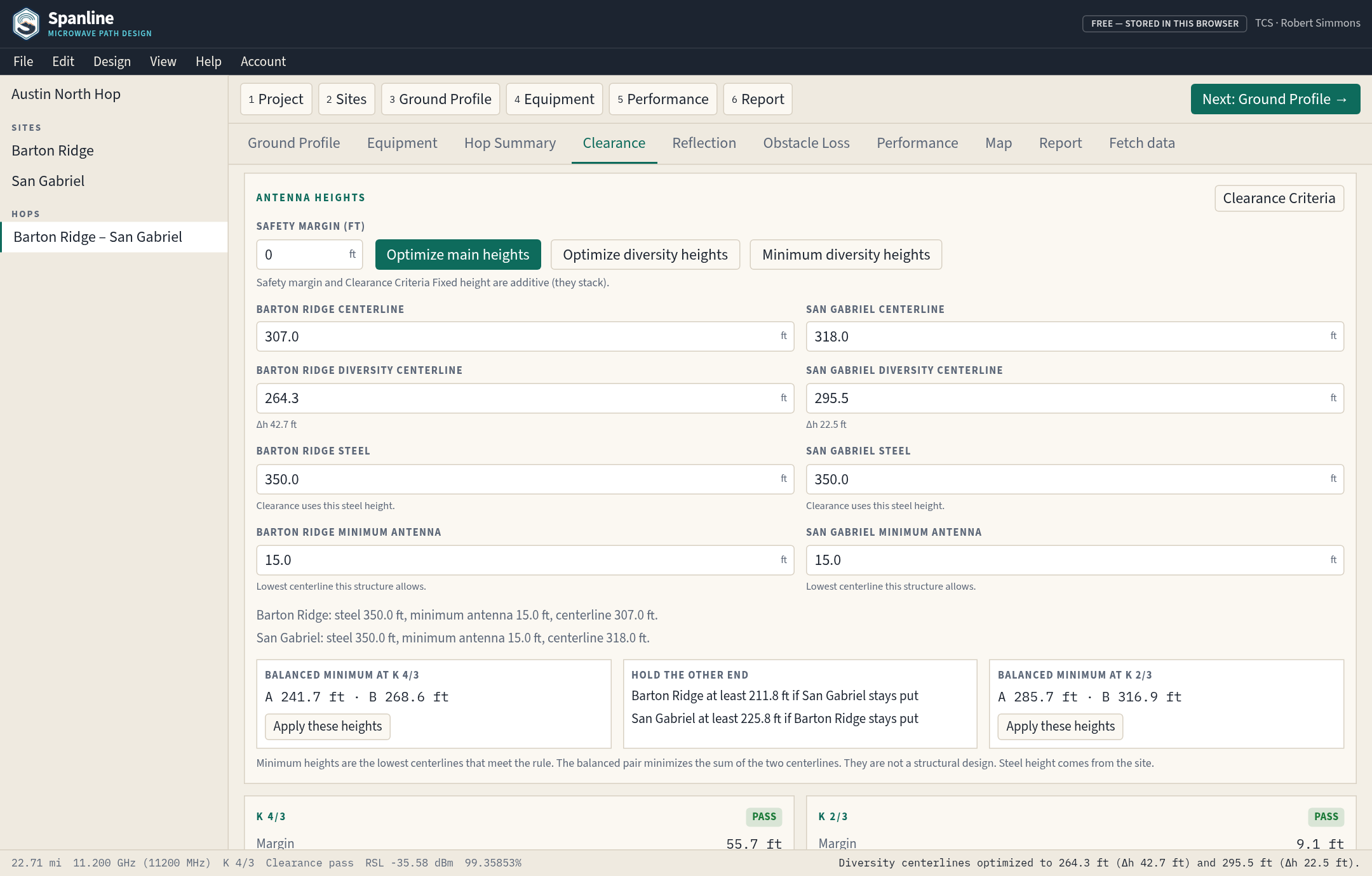
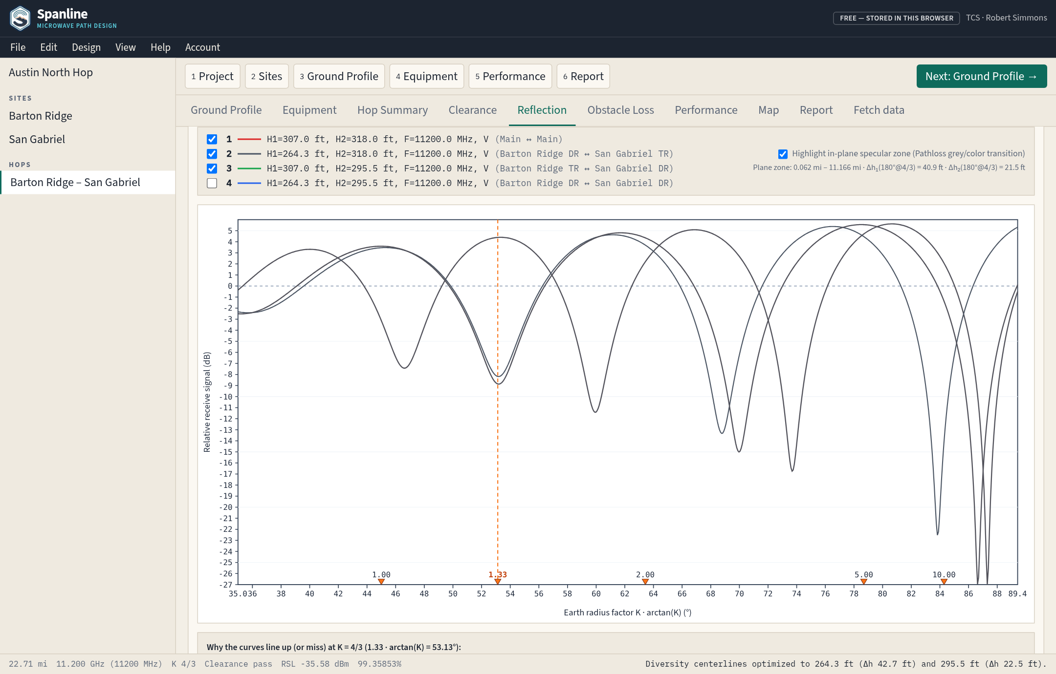
Fits a least-squares Reflective Plane and sweeps K = 0.70 → 100 on a non-linear arctan(K)° axis across 4 Main/Diversity traces. Optimize main heights steps onto a constructive reflection peak (n + 0.5λ, ~ +5 dB) at K = 4/3, and Optimize diversity heights places space-diversity antennas at exact 180° opposite phase (null @ K = 4/3 inside the 25–60 ft waveguide sweet spot).
TERRAIN, CLUTTER, LIDAR & ASR
1-Click Cloud GIS Fetch & FCC ASR Lookup
Fetch bare-earth elevation from USGS 3DEP Seamless 1 m (S1M) first, then 3DEP 1/3 and 1 arc-second (with Copernicus GLO-90 worldwide and the source recorded per station), overlay USGS 3DEP LiDAR Height Above Ground (HAG), measured canopy height from NAIP-CHM 0.6 m or Meta CHMv2 1 m (optionally used in clearance), LANDFIRE canopy height, OpenStreetMap 3D buildings, and Annual NLCD 2025 clutter classes, auto-populate ±2′ (±120″) hop bounding boxes in Fetch Data, and search the integrated US FCC ASR tower database by registration number or coordinate radius.
SITE COORDINATES, FIELD & MOBILE
Coordinate Sources, FCC ±1″ Check & Installable App
Keep Customer Provided, ASR Registration, and Actual Measured coordinates per site and print a Site coordinates report of geodesic deltas and bearings, with a 50 ft flag and the FCC ULS vs. ASR ±1 second note. An ASR number in Site Data shows the FCC record’s coordinates, ground elevation, and offset in Site Coordinates and its report for comparison; the site’s own coordinates never change until Use ASR coordinates is clicked, and that button appears whenever they differ at all. Site coordinates Print / PDF and the ULS draft PCN print from the open page. In the field, use GPS location, a full-screen map, and long-press height notes placed on the hop, track every hop on the network health board, and install Spanline as a Progressive Web App with an offline page.
PASSIVE, ALIGNMENT, CONTROLLING POINTS & ULS
Passive Repeaters, Crew Alignment, Controlling Points & Preliminary ULS Screen
One passive site per hop: billboard far-field gain G = 10·log10(4π·A·cos(α/2)·η / λ²), or back-to-back catalog antennas minus jumper loss, with a separate profile on each leg and a near-field warning. The alignment sheet prints true azimuth, WMM-2025 magnetic azimuth, expected unfaded receive level ±2 dB, a sidelobe band or a labeled 20–30 dB fallback, and a QR card. Controlling points place nominal clearance, minimum-k clearance, and diffraction edges at latitude and longitude. The preliminary FCC ULS screen reads the imported weekly public file and keeps active MW, MG, and CF grants. Production holds a complete import of the 1 Nov 2026 file, source time 9:02:19 AM CST: 399,422 path rows (MW 81,716, MG 151,449, CF 166,257), zip sha256 e3e2033f987e1bc32edf88f5012c54edcb608b20d50a7b49421714938526676d, import id 1, partial 0, capped 0. If none is imported, the server answers: No ULS snapshot has been imported. A missing snapshot is not a clear result. The search reads at most 2,000 rows and lists at most 150. That list is not a nearest set. A loaded snapshot is still not frequency coordination, not a clearance, and not a prior-coordination certification.
CLIENT REVIEW LINKS
Read-Only Review Links Pinned to a Saved Revision
On the paid plan, Project Home > Share for review creates a revocable read-only link pinned to the saved revision, with a 7, 30, or 90 day expiry, an optional passcode, and a scope for the map, profiles, Summary, Report Book, and alignment sheets. The reviewer needs no account. Comments pin to a hop, a site, or a profile distance, and an approve or request-changes decision is listed in version history and printed in the Report Book. Revoke takes effect immediately, and the link leaves out the account, other projects, and licensed-path screening details.
VIEWSHED & REFLECTION REPORTING
Site Viewshed Screening & Reflection Results in the Report Book
Site viewshed screening. Viewshed casts 180 radial rays from a site antenna (5 to 50 mi radius, about 24 stations per ray) over USGS 3DEP terrain and the same clutter and canopy sources a path uses, and colors each cell green when the line to a far-end antenna (default 10 m) clears the project K, Fresnel fraction, and fixed height, amber when it clears only at K = 4/3 or half the Fresnel fraction, and red otherwise. FCC ASR structures in green cells are listed with the mount they need, and Start hop opens a hop from a cell or a structure. The overlay is saved with the project, written to KML, and marked out of date when the site, antenna height, frequency, or clearance criteria change. It is a sampled screening aid, not a path profile or a clearance result.
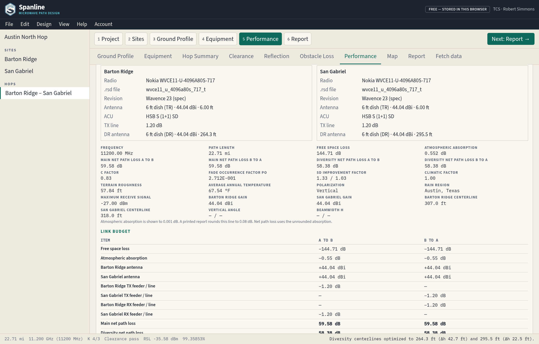
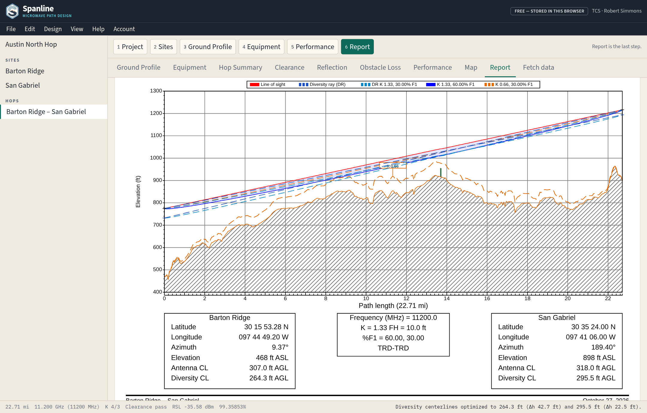
Reflection results in the hop report and Report Book. Reflection planning prints the antenna heights used, a K sweep table and graph, and per-ray tables for Main and each diversity pair, with a sketch that draws both legs of every reflected ray and labels antenna centerline AGL. The link budget recomputes diffraction loss from the current profile, so a path that clears carries 0.00 dB, and the mode selected on Performance is shown on the Equipment radios and bolded in the printouts.
COCHANNEL XPD & PATHLOSS FILE FIDELITY
Pathloss-Matching Cochannel XPD Interference, File-True Imports & Add as New Project
Cochannel XPD interference. A per-hop setting, Off by default, applies the cochannel equations of the Pathloss 5 Program Addendum (eqs. 33–42, based on ITU-R P.530 §4): antenna XPD at each end (entered, else the antenna catalog, else 30 dB), each radio mode’s XPIF, and the radio noise threshold give the multipath and rain XPD fade margins and threshold degradations. Flat fade margin − multipath then drives the multipath outage, and the rain degradation drives the rain outage. On an 11 GHz reference path with 10 modes from 4096QAM to QPSK, every Flat FM − mp row matched Pathloss 5 within 0.012 dB. A .pl5 that stores antenna XPD opens with it On, and export writes it back; Off leaves every result unchanged.
File-true .pl5 imports. A .pl5 opens on the mode Pathloss had selected (the first mode whose operating threshold is within 0.05 dB of the file’s radio threshold), and the dispersive fade occurrence factor starts at 1.00 on every new path while an imported .pl5 or .gr5 keeps the file’s factor.
Add as New Project on import. When the open project already has path data, a .pl5, .gr5, or multi-file import offers Add as New Project (the default), Merge, Replace, or Cancel, so a new file never has to overwrite the open project.
PATHLOSS 5.1 NUMERIC FIDELITY
Pathloss 5.1 Gas, Slant Distance, Crane Rain Search & Wavence 23
Gas, slant distance, and rain. Atmospheric absorption uses the formula on the Pathloss 5.1 help page (oxygen and water vapor, 7.5 g/m³ by default, with no height, temperature, or pressure term), free-space loss uses the Pathloss 5.1 slant distance (manual equation 73) when antenna heights are known, and Crane rain outage uses the Pathloss search: the percent of the year is bisected on 0–1 % and stops within 0.05 dB of the fade margin, with the Crane (1980) 22.5 km modified-probability rule on longer paths. The results are checked against Pathloss 5.1 output on three reference paths.
Pathloss earth radii and rain-table pairing. Profile curvature, clearance, height suggestions, viewshed, vertical angles and reflection use 6,375 km; ITU-R P.526 diffraction and the slant distance use 6,370 km. .pl5 rain tables pair the rate in slot j with the percentage in slot j − 1, just as Pathloss reads them.
Site coordinates and stored lengths. Use Customer Provided coordinates switches a site back from its ASR Registration coordinates without losing either set. Moving a site refreshes every hop length that equalled the old geodesic; Performance offers Use the site coordinates when a stored length is more than 0.5 m from the sites.
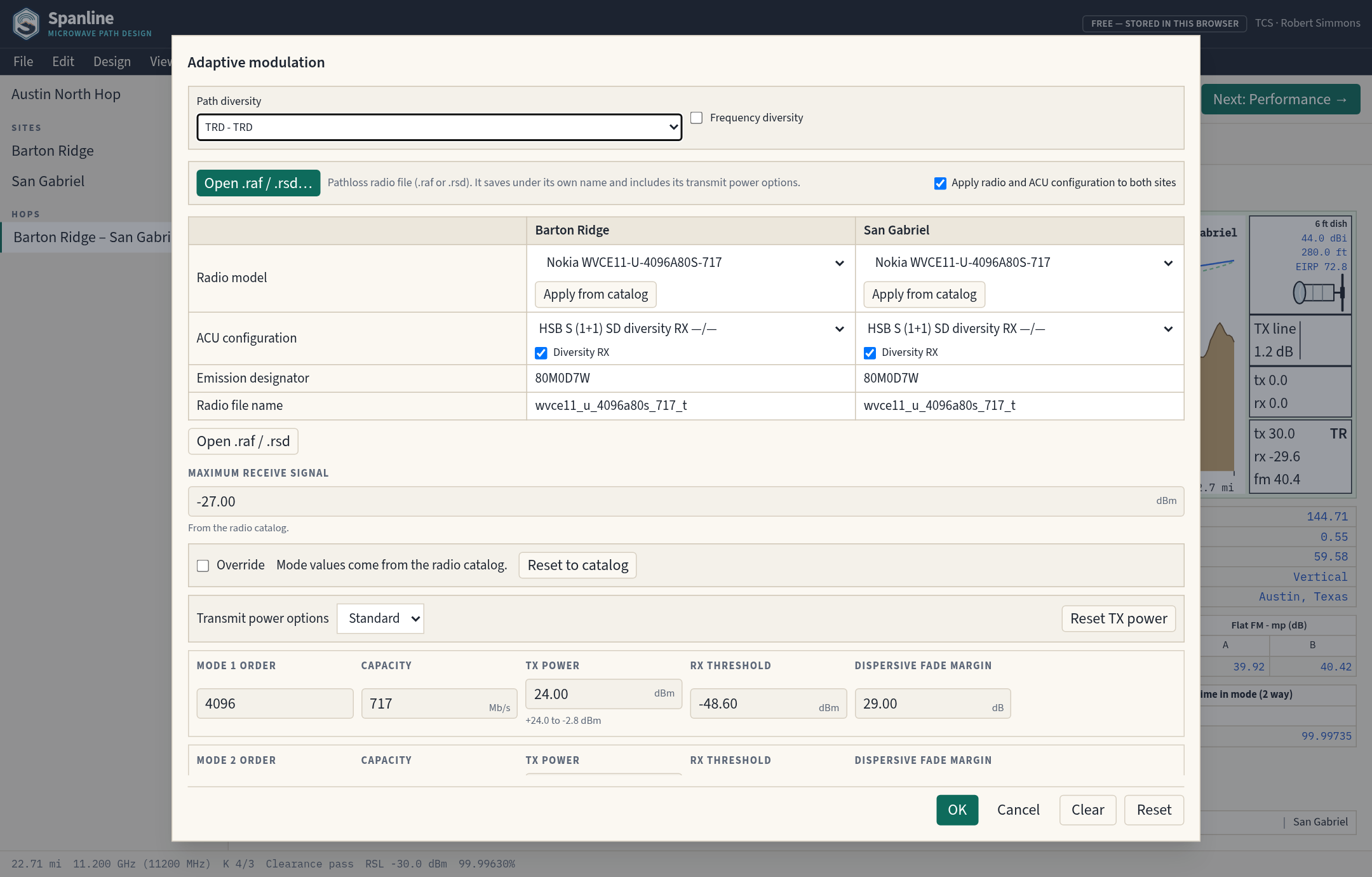
Nokia Wavence 23 radio set with a TX power pick-list. The shared catalog carries the 63 Wavence 23 Pathloss .rsd files. When a radio file carries more than one transmit power option, the hop offers a pick-list (for example Standard or High).
PATHLOSS OPERATION & ROUGHNESS
Microwave / Adaptive Modulation, Roughness Methods & Design Option Save-Over
Microwave or Adaptive Modulation radio operation. Each hop has the Pathloss Microwave / Adaptive Modulation switch. Adaptive Modulation (the default) runs every ACM mode with time in mode; Microwave runs one fixed mode from a per-site table (radio model, emission designator, TX power in watts and dBm, RX threshold, maximum receive signal, and dispersive fade margin), filled from the radio file or typed by hand.
Terrain roughness by sea level reference or least squares fit. Sea level reference measures the 50 profile elevations about their mean; least squares fit measures them about a straight line through the same points, so a steady climb between the ends does not count as roughness. Both values are shown, and fetching elevations or loading a CSV profile recalculates a roughness and C factor that were not typed by hand.
Save over a design option. When the active option is edited it is marked changed, and Update saves the current setup over it (keeping or changing its name); the ⤓ on any other option saves over that one, each as one undo step.
.pl5 export from sites-only files. A .pl5 with sites but no terrain profile takes its distance units from the path length in the file header and exports again in the same units.
FIND TOWERS & RELAYS
Find Towers & Two-Hop Relay Search
Find towers screens nearby FCC ASR structures for line of sight against USGS 3DEP terrain, clutter, earth bulge, and every active clearance rule, solves the lowest clearing mount per structure, and color-codes candidates by clearance and estimated 99.999% availability. Relay mode ranks two-hop relay structures between Site A and Site B by the weaker leg, and Create hop adds the structure as a site and opens the profile.
REPORT BOOK & WORKFLOW
Mixed-Orientation Report Book & Workflow Menus
The Report Book prints the cover and hop profiles in landscape and per-hop link budget pages in portrait in one document. Menus follow the design workflow (File, Edit, View, Path, Equipment, Analysis, Reports, Help, Account), every workflow tab shares one project step bar, and the last-used project opens directly at startup. Space diversity heights solve to 180° opposite Main at the K where Main peaks.
FCC PART 101 & MULTI-HOP C/I
FCC Part 101 Channel Plan, Hi/Lo Audit & C/I Solver
Select from 503 authentic FCC 47 CFR § 101.147 T/R channel pairs (L6, U6, 11, 18, 23, 80 GHz + unlicensed), audit shared relay sites for Hi/Lo TX/RX bucking conflicts, compute a pairwise directed C/I & TIA TSB-10-F Threshold Degradation (TD dB) matrix using actual .ant/.asd RPE patterns and NFD, and run 1-click conflict-free channel auto-assignment.
AUTO-SIZE DISH & POWER
1-Click Auto-Size Dish & Radio Power to Target
Automatically sweep band-matched catalog dishes (1–12 ft, symmetric/asymmetric, FCC Cat A filter), discrete radio TX power options, and TRD-TRD Space Diversity to satisfy 99.95%, 99.99%, 99.999%, or Simultaneous Dual-Target (Protection + Full Capacity) availability goals with 22-step bisection dB margin surplus/deficit and Multipath vs. Rain bottleneck diagnosis.
DELIVERABLES & REPORT BOOKS
2-Page Pathloss, Full & Network Report Books (RTF/PDF/KML)
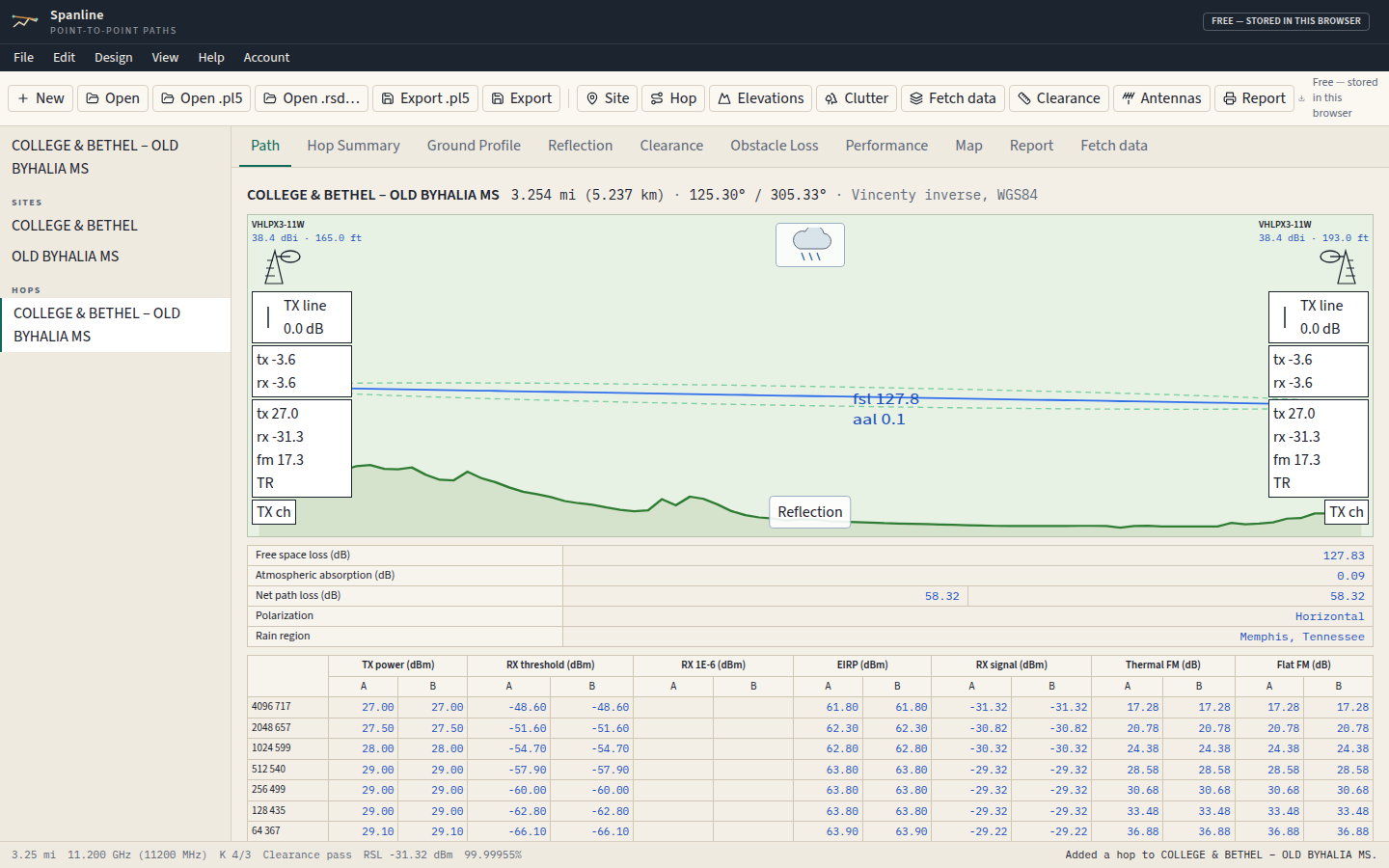
Generate classic 2-page Pathloss 5-style Reports, Full Reports, and multi-hop Network Report Books (Project Network Summary + per-hop link budgets/profiles + aggregated BOM), Microsoft Word .rtf files with native vector EMF path profiles and optional Spanline crest logo, printable PDFs, multi-hop 3D Google Earth .kml files, and BOM .csv spreadsheets. Single-hop reports carry a current-hop map, and each Network Report Book adds a landscape network map page (OpenStreetMap or USGS Topo basemap, vector EMF in .rtf).